Create a 3D Building in AutoCAD
- Lesson 3-1INTRODUCTION TO 3-D (Terminology)
- Lesson 3-2ISOMETRIC DRAWING IN AUTOCAD
- Lesson 3-3WORKING IN 3 DIMENSIONS (X,Y,Z Axes, 3D Rotation)
- Lesson 3-4VIEWING 3-D OBJECTS (Perspective Views, 3D Orbit, DView)
- Lesson 3-5BASIC WIREFRAME MODELS
- Lesson 3-6LINE THICKNESS
- Lesson 3-7REGIONS AND 3-D FACES AND EXTRUDING
- Lesson 3-7aMORE ABOUT EXTRUDING & LOFTING
- Lesson 3-8REVOLVED OBJECTS - REVSURF AND REVOLVE
- Lesson 3-9ADDING MATERIALS IN AUTOCAD
- Lesson 3-10PRIMITIVE SOLIDS
- Lesson 3-11BOOLEAN OPERATIONS AND 3D EDITING
- Lesson 3-12CHANGING FROM THE WCS TO THE UCS
- Lesson 3-13MAPPING MATERIALS
- Lesson 3-14CREATING NEW MATERIALS
- Lesson 3-15EXTRA PROJECTS AND A TUTORIAL
- Lesson 3-16PUTTING IT ALL TOGETHER - MODEL A BUILDING
- Lesson 3-17INTRODUCTION TO RENDERING AND LIGHTING IN AUTOCAD
- Lesson 3-18CREATING ANIMATIONS IN AUTOCAD
- QUIZ FOR LEVEL 3 - 84 QUESTIONS
Topics covered in this Lesson:
Create a 3D Model of a Building
If you have completed the previous lessons in this level, you now have the tools to create a large variety of objects in 3D. This lesson is designed to show how to create simple building in 3D from start to finish. The same process can be used to build more complex buildings as well. Start by creating this building and then try drawing your home.
This method follows my usual approach of "modeling it like you would build it". I'll start with a floor plan, then build the walls, make openings for the doors and windows, add doors and windows, then put a roof on it. It just seems like the most logical approach to me.
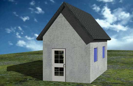
Below is an image of the final building that is drawn in this lesson (with rendering and lighting explained in the next lesson).
Start by setting your units to architectural (DDUNITS). I apologize to everyone in advance that uses the metric system, but most of the viewers and revenue come from the USA, which still refuses to learn the metric system. These techniques will work with any floor plan, so if you have one with metric measurements, feel free to use it.
Remember to create new layers for each type of objects you will draw (windows, doors, walls, roof, etc).
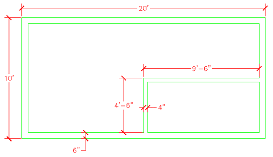
Now draw the bases of the walls using the dimensions are shown below. You don't need to dimension it. Optionally, you can use the (new in AutoCAD 2007) POLYSOLID command.
Now you will create regions out of all your wall lines.
Command: REG REGION
Select objects: <SELECT ALL THE LINES> Specify opposite corner: 7 foundSelect objects: <ENTER>
3 loops extracted.
3 Regions created.
You should now have 3 regions. If you don't then it usually means the your lines don't meet.
Next you are going to EXTRUDE the walls 9' high.
Command: EXT EXTRUDE
Current wire frame density: ISOLINES=4
Select objects: <SELECT THE 3 REGIONS> Specify opposite corner: 3 found
Select objects: <ENTER>
Specify height of extrusion or [Path]: 9'
Specify angle of taper for extrusion <0>: <ENTER>
It should appear that nothing has happened. You will need to go to the SW Isometric view to see how the wall were extruded. Do this and then use the HIDE Command. Something doesn't look right. What you will need to do is Subtract the 2 smaller regions from the larger region. You should see this result after the Subtract and Hide commands.
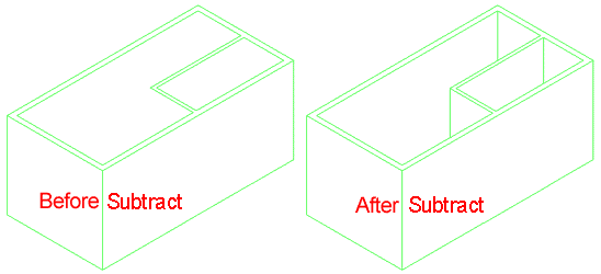
Now it's starting to look like something. Your walls are almost complete.
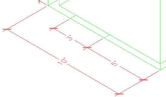
Next you will add a door or two. The first door, on the outside will be on the bottom left wall. Start by drawing a rectangle from the middle of the outside wall and the other corner @6,36 - this will create the opening. Your rectangle should look like this:
Now you want to EXTRUDE the rectangle up 6'8" and SUBTRACT it from the wall.
Create a door layer (or make it active if you already have one) and draw a rectangle in the door opening that is 3"x 3' - put it in the middle of the door opening. Extrude it 6'8".
Now create a second door (and opening) on the inside wall parallel to the outside wall that is 32" wide. After you do that, the drawing should look like this from the SW Isometric view:
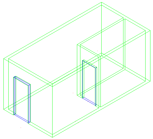
If you haven't saved your drawing yet, now would be a good time.
Now you're going to add some windows. This will be done using a similar process as the door. You will create openings, then add the window.
Create 2 rectangles in the position shown below.
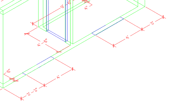
EXTRUDE the window 36 inches. Them move them up 3'8" in the Z axis. Remember your relative coordinates from Lesson 1-1?
Command: M
MOVE
Select objects: 1 found
Select objects: 1 found, 2 total
Select objects: Specify base point or displacement: <PICK ANYWHERE ON SCREEN>
Specify second point of
displacement or <use first point as displacement>: @0,0,3'8
Now mirror the bottom left box to the opposite wall (Note: It will be easier if you revert to the top view for the mirror command)and the upper box to the inside wall so you have the 4 boxes looking like this :
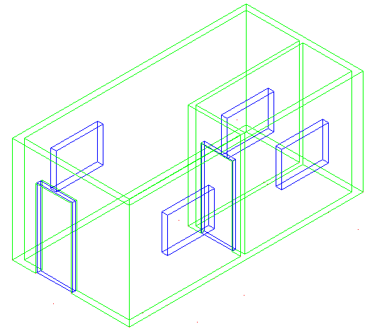
Next, subtract the four window openings from the walls. After switching to SW Isometric view and using the hide command, your drawing should look like this:
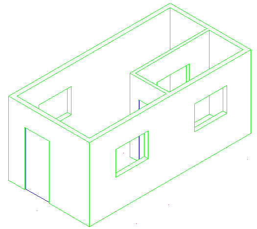
Now the window panes have to go in. Since this is a simple drawing, you just be putting in a plane of glass to represent the window.
Create a new layer for windows. The easiest way to do this is just like you created the doors. Make the window 1" deep. Once again, start with the rectangle at the base of the window opening, extrude it the height of the window opening and move it into the centre.
Once you have one window made, copy it to the other openings. Save your drawing and then type in SHADE and choose the G option. Your building should look like this:
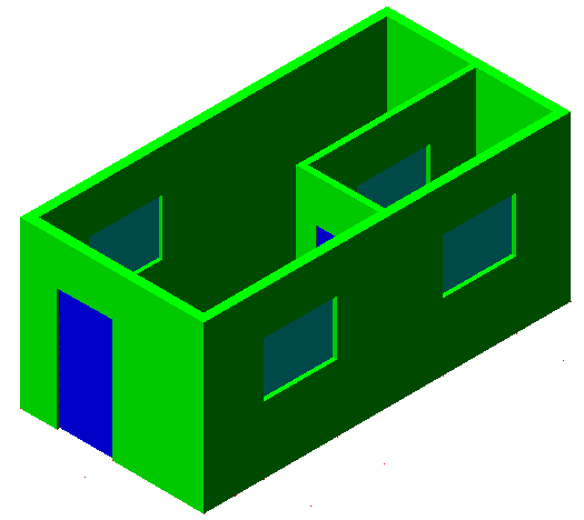
Wow - now you're getting there. Next you will add to the walls to make them the right pitch for the roof.
First you will have to change your UCS. Start he UCS command and choose the 3Point option by typing 3 <ENTER>. When prompted (watch the command line) select the points shown below:
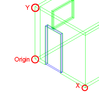
After you pick the third point, the cursor should turn on its side. Now you can draw on the side of the building. In this case, you will be drawing a triangular shape to represent the rest of the wall up to the roof.
Draw a LINE from the middle of the top outside of the wall up 6'. Then draw a POLYLINE from one corner, to the next, to the top of the line and use the C option to close the polyline.
Finally EXTRUDE the triangle -6" and then COPY the extruded object to the other side of the building. Erase the vertical line you drew. You should have something like this now:
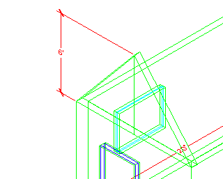
To finish the wall, perform a UNION (Lesson 3-11) between the triangular sections and the bottom wall.
You're almost done now. You will need to draw the roof to complete the drawing.
First you will need to change your UCS to align it with the slant of the roof. Use the points shown below - and be careful which endpoints you select.
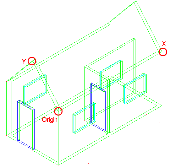
Now draw a RECTANGLE from the top left corner of the triangular shape to the bottom of the opposite corner of the other triangular shape. It should like the magenta rectangle below:
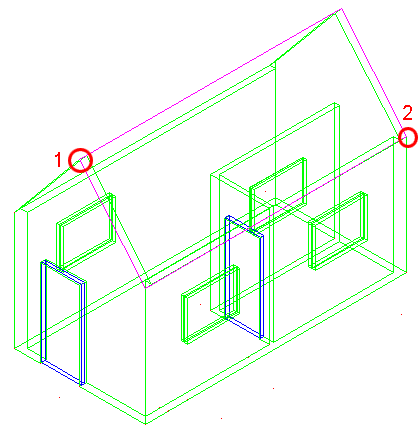
New EXTRUDE the rectangle 6". Then copy 12" down in the Y Axis and then copy it 12" up in the Y Axis - when you have the 3 sections UNION them into one object.
Change back to the WCS (UCS <ENTER><ENTER> ) and mirror the roof object to the other side. Check that it looks correct by viewing the model from the left and from the front.
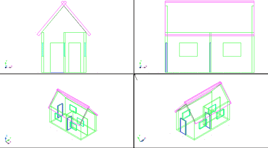
The last thing to do is trim the excess pieces off the top of the roof where the two slabs intersect. This will be done using the SLICE command (Lesson 3-11).
Go to the SW Isometric view.
Start the SLICE command and select the roof section towards the back. Then when you are asked to pick three points on the slicing plane, select any three points on the top of the roof section at the front.
Switch to the NW Isometric view and slice other roof section in the same manner. Check to see that your roof looks correct, and if it is, union the two roof objects now.
Go to the WCS and copy the roof 12" in the Positive X Axis and 12 " in the Negative X Axis and then union all 3 roof objects. Your building should now look like the one below:
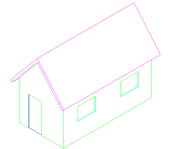
Your building is complete. To add a lawn , draw a very large rectangle around the house at the same Z level as the bottom of the house. Then turn it into a region so that materials can be added later.
Save the drawing, then if you like, add materials and render the final image. In the image at the top of the lesson, the door is detailed material. More detailed instructions for rendering will be found in Lesson 3-17.
Here are the materials used for the rendering at the top of the page. You can download them and add them to your Textures folder. The door texture would be used like the stop sign you may have rendered in lesson 3-14.
door.jpg | grey_roof_slate.jpg | grass.jpg | stucco_white.jpg
You can also try to add more detail to the building if you like. But now you can see that using a few commands (in this case about 12), you can draw decent looking models.
Extra Practice: Build a 3D model of the Cabin Drawing from Lesson 2-1. How much detail can you add? Door knobs? Window panes?
Video: Model a Building in 3D
You Scored:

Fun fact: 100% of Fortune 100 companies are AutoDesk customers.

- To cover this months server costs
- Exceeding amounts will go to creating new content
- Even a penny will help
Did you like the lesson? ❤️
