Viewing in 3D Dimensions
- Lesson 3-1INTRODUCTION TO 3-D (Terminology)
- Lesson 3-2ISOMETRIC DRAWING IN AUTOCAD
- Lesson 3-3WORKING IN 3 DIMENSIONS (X,Y,Z Axes, 3D Rotation)
- Lesson 3-4VIEWING 3-D OBJECTS (Perspective Views, 3D Orbit, DView)
- Lesson 3-5BASIC WIREFRAME MODELS
- Lesson 3-6LINE THICKNESS
- Lesson 3-7REGIONS AND 3-D FACES AND EXTRUDING
- Lesson 3-7aMORE ABOUT EXTRUDING & LOFTING
- Lesson 3-8REVOLVED OBJECTS - REVSURF AND REVOLVE
- Lesson 3-9ADDING MATERIALS IN AUTOCAD
- Lesson 3-10PRIMITIVE SOLIDS
- Lesson 3-11BOOLEAN OPERATIONS AND 3D EDITING
- Lesson 3-12CHANGING FROM THE WCS TO THE UCS
- Lesson 3-13MAPPING MATERIALS
- Lesson 3-14CREATING NEW MATERIALS
- Lesson 3-15EXTRA PROJECTS AND A TUTORIAL
- Lesson 3-16PUTTING IT ALL TOGETHER - MODEL A BUILDING
- Lesson 3-17INTRODUCTION TO RENDERING AND LIGHTING IN AUTOCAD
- Lesson 3-18CREATING ANIMATIONS IN AUTOCAD
- QUIZ FOR LEVEL 3 - 84 QUESTIONS
Topics covered in this Lesson:
Viewing Objects in 3 Dimensions, Tiled Viewports, Perspective Views, 3D Orbit
AutoCAD has a few ways for you to view an object other than the plan view that you have used for your 2-D drawings.
Now is a good time to change into the 3D Basics Workspace. Click the 'gear' icon on the status bar and select "3D Basics".
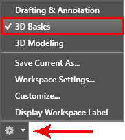
When you are in the 3D Basics workspace, your tool palettes on the ribbon will change. This will make it easier to find tools and icons that you'll use more often in 3D.
The first one we'll look at is the Visualize Palette.
.gif) >
>
I find this is the quickest way to learn the different views, and I'll show another way in a minute, but for now this is the fastest and clearest way to see different views of your AutoCAD objects in 3D.
Open this DWG file and then we'll look at it from a few different angles.
When you first open it, you'll see the drawing from the plan (top) view looking straight down the Z axis towards the origin. You'll see the X axis in its familiar location with positive to the right and the positive Y axis pointing up.
Using the Visualize tools shown above, select the Bottom View. You'll now be looking up from the Negative Z axis towards the origin.
.gif)
Notice how the Positive X axis is now pointing to the left? And it's backwards? You're looking UP now instead of DOWN. It's simple to see in this example, but what if you were looking at a cube? (It would look the same from top or bottom.) Have a look at your UCS Icon - check its orientation, because even if you view changes, your UCS / WCS doesn't necessarily change with it. This is REALLY important to pay attention to when you start drafting in 3D.
Try a few other views from this list like the SW Isometric view, then return to the Top view.
Tiled Viewports
There will be times when you may need to see around to the other side of your object. Then you can easily use the other preset views to see your model. You can also have more than one view on your screen at a time.
To achieve this, use the Viewport Configuration option of the Visualize tool palette and select the "Four: Left" option. Any view or viewport configuration can be saved under a unique name. Later you can easily restore this view when needed. Here are the preset viewport configurations that you can use in model space.
.gif)
Change the view by picking in one of the viewports and selecting a new view in the droplist. See if you can get this same configuration in your drawing.
Here are a few general notes about views and viewports:
You can have viewports in either model space (tiled) or paper space (floating).
They can have different zoom ratios.
There is a difference between views and viewports.
If you go to a lot of work to get a view you need, save it using the VIEW command.
When saving a view, give it a descriptive name.
Keep an eye on the UCS icon in the corner of the screen or viewport.
The smaller your monitor is, the harder it is to see tiled viewports.
When you have more than one viewport, click inside the one you want active.
Change back to a single tiled viewport and go to the top view. On the right your screen you should see the "View Cube" This is a quick tool that lets you change your view with a click or two using a visual cube for reference and orientation.
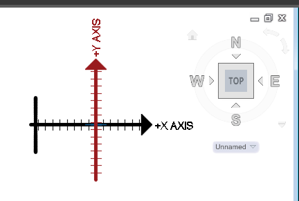
To use the View Cube, you can click on different sections of the cube or on the directional letters. You can also select a corner of the View Cube to change to isometric views. In the example below, the highlighted corner will give you the SW Isometric view.
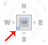
If this is confusing, that's understandable, but notice how the highlighted corner is between the W (West) and S (South) views? Click around on the cube and see if the views you get are what you are expecting. Once again, it will take a while to be comfortable viewing in a 3D world (on a 2D monitor).
For more practice viewing your 3D drawing, open up up this sample 3D file of a table and chairs. Change to different viewport layouts as shown above. Try some of the different Isometric views. Depending upon the size of your monitor, it may not be practical to use multiple viewports. In the end it is a matter of personal preference that decides what setup you are comfortable drawing in.
When you're finished exploring, change back to 1 viewport and switch to the SW Isometric view. Also, if you need to, change to 2D wireframe in your Visual Styles tool palette.

Prespective Views
There is another command called DVIEW (Dynamic View) that gives you more control over the view of your objects. It will also allow you to see a perspective view of your model. This can be a very confusing method if you don't have a system. What follows is my approach to creating perspective views.
The basis of generating a perspective view is to have a virtual camera and target. Think of where you would like to 'stand' (the camera) and what direction you want to look at (the target).
In this example, I want a view that gives me slight perspective view of the table and chairs. The first thing I need to do is draw a point for my camera location.
Draw a line from the centre of the bottom leg 6' in the negative X axis. Now draw a line 5'6" straight up (@0,0,5'6) and finally draw a line to the middle of the far end of the table. It should look like this:
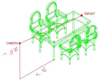
Now start the DVIEW command. You will be asked to select objects. You can select everything, or for the purposes of setting points, I would normally just choose the line as it makes the command faster in large drawings.
Start the command and then select the line. You'll have a bunch of options on your command line now, but you want to select POINTS (PO). This allows you to select a target and a camera, AutoCAD will aim the camera at the target and give you a perspective view. Follow the steps below to try this out.
Command: DV DVIEW
Select objects or <use DVIEWBLOCK>: <SELECT THE LINE> 1 foundSelect objects or <use DVIEWBLOCK>: <ENTER>
Enter option
[CAmera/TArget/Distance/POints/PAn/Zoom/TWist/CLip/Hide/Off/Undo]: PO <ENTER>Specify target point <84'-0", -113'-7 9/16", 4'-2 7/16">: <PICK THE ENDPOINT ON THE RIGHT (TARGET)>
Specify camera point <66'-10 11/16", -130'-8 15/16", 21'-3 13/16">: <PICK THE ENDPOINT ON THE LEFT (CAMERA)>
Enter option
[CAmera/TArget/Distance/POints/PAn/Zoom/TWist/CLip/Hide/Off/Undo]: <ENTER>
Regenerating model.
Start the DVIEW command again and select all the objects. In larger drawings, select the objects
that are furthest to the extents of the drawing (this will save time and let you know the limits
of your view) and any objects that
are critical to your view. What this means in that if you are using the command on a very large
drawing, the DVIEW command can slow down your system to a crawl. By selecting only the ones on
the outside limits of your drawing,
you will still be able to use the command quickly and efficiently.
This time, choose the Distance option by pressing D <ENTER>. This option effectively
zooms in and out while in a perspective dynamic view. Move the slider at the top until it is
just right of the '1x' and then left
click with your mouse. Note that slower computers will take longer to regenerate the drawing for
you. You can also enter distances manually on the command line - try this out as well. Each 3D
model will require different settings
to get the view you want.

While still in the Dview command, type in PA for the Pan option and move the table and chairs up slightly in the drawing area so that they are centered.
And lastly, type in H for the hide option for a more realistic view. and then press <ENTER>.
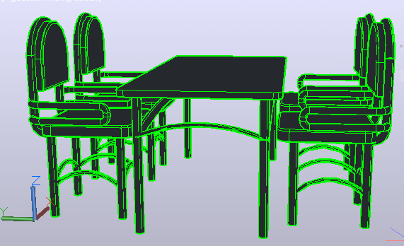
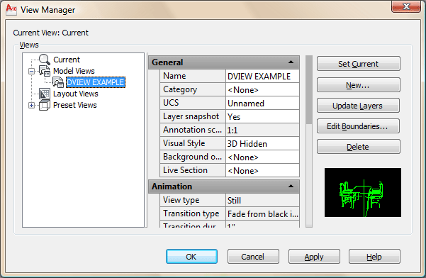
To preserve this view that you worked so hard to achieve, type in V (for view) and select the New button and give your view a name and press OK. Now when you need to go back to this view you just type in V again, select your named view, press the Set Current button and press OK. Your new view is also added to the top of the list in your View Tool Palette.
If you are using this command on larger drawings, like a home or building, the same process is used, but you should create the camera location to be further away from the objects you want to view. Practice makes perfect and this command can take some trial and error sometimes to get it just right. In the end, it is a very powerful viewing tool. When practicing, save views so you can go back to them if needed - it will save you a lot of time.
3D Orbit
Another way of viewing your objects is to use the 3DORBIT command. This will give you a free hand to rotate your drawing around in space. Type in 3DO <ENTER> and you'll see that your cursor changes and you can start rotating your objects around freely by clicking and moving your mouse. You can always reset your view as you learned above.
This is a handy way to quickly view your drawing and see if there is anything that doesn't look 'quite right'. You might find lines that snapped to the wrong OSnap or other errors using this command. When it comes to generating views, I still recommend the DVIEW command so that you have more control over what your view will look like.
Video: Using DView to create perspective views
You Scored:

Fun fact: Under Bartz's 14-year leadership, Autodesk's gross annual revenue grew from $285 million to over $1.5 billion. She became Chairman of the Board in 2006 and the company kept growing. She left in 2009, and after a few months rest, she was approached to become CEO of Yahoo.

- To cover this months server costs
- Exceeding amounts will go to creating new content
- Even a penny will help
Did you like the lesson? ❤️
